
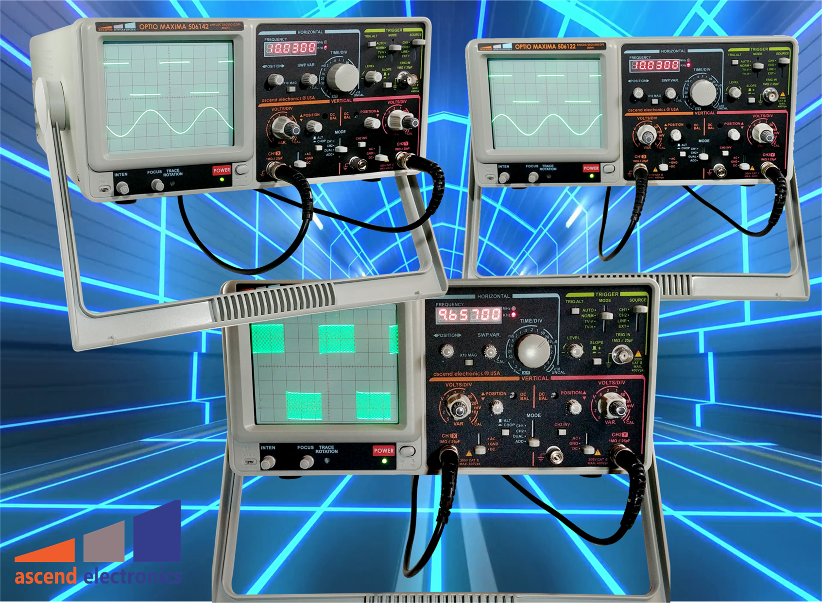
ASCEND ELECTRONICS® LABORATORY OSCILLOSCOPES
Ascend Electronics® Oscilloscopes, sometimes just referred to as scopes, together with multimeters and power supplies are essential tools on any electronics workbench. An oscilloscope is an electronic test instrument that displays the value of an electric signal over time. The display of the oscilloscope shows the amplitude as a voltage of a signal and its time along.
Overview Oscilloscope
Although the signal in the oscilloscope is a voltage, it represents physical properties such as power, current, G-force, pressure, magnetic flux, and acceleration. It needs only the right type of sensor to transform the physical properties into a voltage signal. Even the human voice displays on an oscilloscope by just using a microphone.
Oscilloscopes are the preferred tool to:
• Measure the shape of a waveform (a graph of voltage over time)
• Measure the amplitude and frequency of a signal
• Detect glitches, noise in a signal and distortion
• Measure signal phases
• Measure signal bandwidth, fall and rise times, time intervals
Oscilloscopes are used in the sciences, medicine, engineering, automotive and the telecommunications industry. General-purpose instruments are used for maintenance of electronic equipment, manufacturing test and laboratory work.
Our oscilloscope commitment to you
• Most cost-to-performance efficient oscilloscopes
• Designed to serve you for most of your applications
• Stay productive with easy-to-use professional oscilloscopes
• Highest accurate measurements of your signal’s true characteristics
• Highest signal integrity with low oscilloscope noise
• Give you high flexibility, versatility, and scalability in tools selection
• Providing you we our decades of know-how and expert-level
ANALOG vs. DIGITAL OSCILLOSCOPES
There are two major oscilloscopes: CRTs (Cathode Ray Tube) oscilloscopes, also known as analog and digital oscilloscopes. However, most modern oscilloscopes are digital oscilloscopes. Digital Storage Oscilloscopes (DSO) read a voltage on the input channel, amplify and condition the signal, and finally convert the signal with an Analog-To-Digital converter (ADC). The ADC samples the voltage into an n-bit sample at every predefined time interval.
These samples are then passed through filtering and algorithms before being stored in the scopes memory and displayed on the screen. This digitalizing creates some limits to the performance of a digital scope. The sampling frequency (given by the sample time interval) and code resolution create aliasing of the waveform and limit the maximum signal frequency of the system. In addition, the sampling rate creates gaps in the signal. Increasing the ADC's sampling speed results in smaller gaps in the waveform record and increases the Nyquist frequency, which improves aliasing. The total number of codes (2 to the power of n-bit) defines the produced voltage resolution. A higher voltage resolution and frequency permit a smoother and more accurate reproduction of the input waveform but exponentially increase the tool's cost and complexity. Digital scopes display systems also exhibit significant dead- or blind times, based on the scopes processor's ability to display the waveform data only after the CPU has finished all its operations.
This CPU performance situation can result in an unresponsive waveform display of random events since the scope cannot follow changes in the input signal. On the other hand, analog oscilloscopes do not sample the waveform and are, therefore, not limited to those digital limitations. The signal is first attenuated, amplified, and then fed directly into the Cathode Ray Tube.
As a result, CRTs display a more accurate waveform. CRTs don't have a considerable dead time since they continuously display the signal, so random signal abnormalities can easily be found. The frequency bandwidth of the analog amplifier is the limiting factor for the signal bandwidth. A significant advantage of the digital scope over its analog brother is that the waveform can be stored and reused any time later. Furthermore, with the help of mathematical algorithms and a CPU, the signals can be changed into another domain, for example, into the Frequency domain, with the help of Fast Fourier Transformation (FFT).
Both analog and digital oscilloscopes have advantages and disadvantages. In comparison, a digital scope's cost is approximately five times more expensive than its analog counterpart with the same signal precision. A huge advantage of analog scopes over their digital brothers is that their much easier to use and have low learning curves. The correctness of the signal certainty is higher. Debugging is often faster and easier going analog, whereas specification of a component under test the digital scope provides more easy-to-read information. It is recommended that a dissent workbench always must have both types of oscilloscope handy and ready to operate. Furthermore, the analog oscilloscope is the preferred tool in a manufacturing environment because of its more straightforward use and manipulation.


