Your RFQ selecting or design an Ascend Electronics® 3 Phase Transformer
With the below Form, you can request a quotation (RFQ) for a new design or let us select an existing Ascend Electronics 3 Phase Transformer that matches your requirements.
The Form allows you to provide us with the first requirement set to select your 3-phase transformer request. Three-phase power transformers are best for electrical systems that require efficient distribution capacity and high-power transmission capabilities. Like single-phase transformers, a three-phase transformer utilizes single-phase alternating current, meaning the transformer relies on a voltage cycle that operates in a unified time phase. We will ask you about the type of power source, frequency, input and output configurations, and other parameters to evaluate the design specification. So let's get started.
The buttons to the right provide Pup-Up-Links to the definitions you need when specifying your design.
An autotransformer has a single winding with two end terminals and one or more terminals at intermediate tap points. It is a transformer in which the primary and secondary coils have part of their turns in common. The portion of the winding shared by both the primary and secondary is the common section. Autotransformers have no galvanic isolation!
An isolation transformer is a transformer used to transfer electrical power from a source of alternating current (AC) power to some equipment or device while isolating the powered device from the power source, usually for safety reasons (or to reduce transients and harmonics). Isolation transformers provide galvanic isolation. Therefore no conductive path is present between the source and the load.
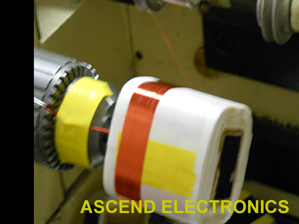
A toroidal transformer is an electrical transformer constructed with a torus or donut-shaped core. Its primary and secondary windings are wound across the entire surface of the torus core, separated by an insulating material. This configuration minimizes the magnetic flux leakage. All Ascend Electronics toroidal transformers are constructed as isolation transformers.
Air-core transformers are designed to transfer energy or radio-frequency currents (currents used for radio transmission). Air-core transformers consist of two or more coils wound around a solid insulating substance or on an insulating coil form and have no magnetic core. Therefore, air-core transformers have a weak energy transmission ratio.
The ratio of a transformer's output power to its input power is known as transformer efficiency. The effect of transformer losses is measured by transformer efficiency, typically expressed as a percentage.
Transformer voltage regulation is the ratio or percentage value by which a transformer's output terminal voltage varies either up or down from its no-load value due to variations in the connected load current.
Transformer temperature rise is defined as the average temperature rise of the windings above the ambient (surrounding) temperature when the transformer is loaded at its nameplate rating.
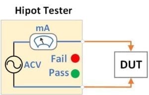
The high-voltage isolation class is used during the transformers' high-pot tests. High-pot (High Potential) tests, also known as dielectric withstand tests, are used to apply high voltage to assets to determine the adequacy of the electrical insulation to withstand voltage transients and ensure the insulation is not marginal. In addition, the voltage class is used to define high-voltage potential differential operation between primary and secondary.
The transformer induces power or signal voltage waveforms for each secondary output. The resulting output waveform will be the same shape and frequency as its input waveform. Note that all transformers have bandpass characteristics, meaning they have a low-end and high-end frequency roll-off. Therefore for transformers outside the standard AC power line (50Hz to 400Hz), such as audio (20Hz-20kHz) and switching (1kHz to 10MHz), the minimum and maximum frequency of the bandwidth must be specified, in addition to the input waveform, such as pulse (square) or sinus.


